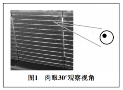
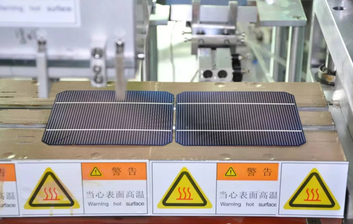
Cause analysis and treatment methods of virtual welding in string welding machineIssuing time:2024-05-08 15:55 In response to the common problem of virtual welding in string welding machines for photovoltaic modules, Zhongbu Qingtian New Energy has conducted a comprehensive analysis of the causes from various aspects and proposed corresponding solutions for the string welding equipment end. We hope that through the sharing of this article, it can help engineers from component manufacturers to identify the cause of virtual soldering problems in a more timely manner and reduce the occurrence of such problems. 1、 Determination of virtual welding What is virtual soldering? The welding strip on the battery cell was not welded to the main grid line of the battery cell, resulting in a small piece of battery cell unit being unable to contact the conductive wire, thus forming a circuit break phenomenon.
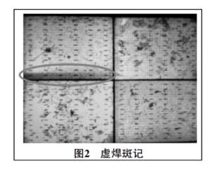
Method 2: EL detection
EL devices use the principle of electrically generated light, which takes photos through a camera and then combines them into a complete image.
A symmetrical dark region along the main gate direction appears on the battery cell, which is determined to be a phenomenon of virtual soldering, as shown in Figure 2.
3、 Types of virtual soldering According to the different positions of virtual welding, virtual welding can be divided into the following types: Zhengxu The welding strip on the front of the battery cell was not welded to the main grid line of the battery cell. Head deficiency The welding strip at the beginning of the battery was not welded to the main grid line of the battery cell. (Belonging to a type of positive and negative, appearing in the front recessed area) Anti virtual The welding strip on the back of the battery cell was not welded to the main grid line on the back of the battery cell. Tail Void The welding strip at the tail of the battery cell was not welded to the main grid line of the battery cell. (Belonging to a type of positive and negative, appearing between the spacing between pieces)
五、 Analysis and treatment methods of the causes of positive and negative phenomena 1. Welding temperature: The welding temperature is not sufficient, and the power of the corresponding position of the lamp tube in this area needs to be increased. 2. Welding time: The welding time is too short and needs to be increased. 3. Welding position: a. The welding head is positioned too high and needs to be lowered in height.
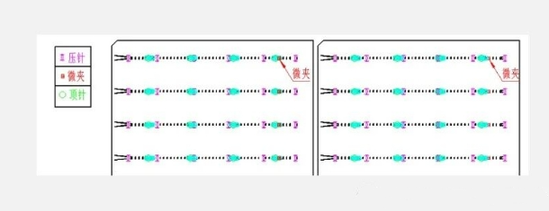
c. The soldering flux has been baked dry. d. The flux replenishment system is malfunctioning and requires inspection and adjustment of the replenishment system. 6. Needle position: a. The left and right positions of the pressure needle are not suitable. The distance between the pressure needle and the welding inventory is too far, especially the distance between the head and tail pressure needles and the welding inventory should not exceed 1.5mm. The welding strip and grid wire are not in reliable contact, and the position of the pressure needle needs to be checked. b. The stuck/detached pressure pin causes poor contact between the battery cell and the solder strip, and it is necessary to check whether the pressure pin parts are normal. 7. Solder strip: The thickness of the solder layer on the solder strip is insufficient, and the stretching ratio needs to be reduced appropriately. Check whether there is any scraping of tin in the solder strip channel. 8. Silver paste: The silver paste of the battery cell does not meet the welding requirements.
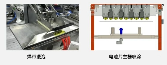
5. Welding table/lower module temperature: Insufficient welding table/lower module temperature often occurs at the beginning of welding. 6. Pressure tool temperature: Insufficient pressure tool temperature during initial welding can easily cause rebound. Temperature compensation function can be used. 7. Flux&Sponge: a. The concentration of soldering flux is low. It is necessary to increase the drying temperature of the flux to increase the concentration of the flux. b. The problem with the material of the flux sponge has caused changes in the characteristics of the flux, resulting in poor solderability. It is necessary to replace the auxiliary agent sponge. c. The soldering flux has been baked dry. d. The flux replenishment system is malfunctioning and requires inspection and adjustment of the replenishment system. 8. Module ejector pin: The module ejector pin is not in place, and the solder strip has poor contact with the battery cell. Check if the ejector pin is stuck and if the left and right positions of the module are not aligned with the battery cell. 9. Welding strip: a. The thickness of the solder layer on the solder strip is insufficient. It is necessary to reduce the stretching ratio appropriately and check whether there is any scraping of solder in the solder strip channel. b. Check if the welding strip has fallen into the groove. 10. Silver paste: The silver paste of the battery cell does not meet the welding requirements. 11. Battery Cell Placement Position: The battery cell placement position is not suitable. Check if the back of the battery cell soldering inventory corresponds to the module ejector pin.
6. Needle position: a. The position of the pressure needle is not suitable. Need to check the position of the pressure needle. b. The stuck/detached pressure pin causes poor contact between the battery cell and the solder strip, and it is necessary to check whether the pressure pin parts are normal. c. Do not fully press the first silver paste point with the welding needle relative to the first starting point of the battery cell, as it will block the flow of tin. The head pressure needle should be pressed 0.5mm on both sides of the silver paste point, so as not to block the flow of solder and facilitate welding.
聲明:此篇為中步擎天原創,轉載請標明出處鏈接:http://www.npcnn.cn/en/sys-nd/47.html
|


